X1 Pro Gen 3: Pin Layouts
X1 Pro Gen 3 Pin Layouts
CYC X6 Controller Pin Layout
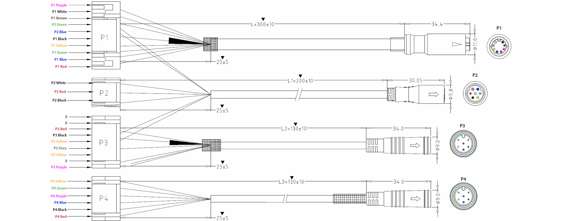
Peripheral Wire Connection (P1)
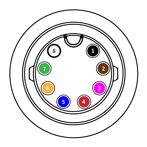
Connection Number | Display Connection | Wire Color |
1 | GROUND | Black |
2 | THROTTLE | Brown |
3 | 5V DC | Purple |
4 | VCC | Red |
5 | KEY LOCK | Blue |
6 | UART RX3 | Yellow |
7 | UART TX3 | Green |
8 | BRAKE | White |
Speed Sensor Connection (P2)
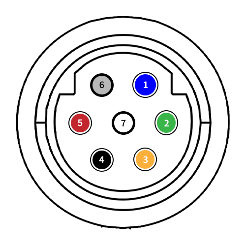
Connection Number | Display Connection | Wire Color |
1 | UART TX2 | Blue |
2 | UART RX2 | Green |
3 | SWCLK | Yellow |
4 | GROUND | Black |
5 | 5V DC | Red |
6 | SWDIO | Gray |
7 | SPEED | White |
Torque Sensor Connection (P3)
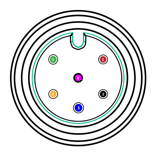
Connection Number | Display Connection | Wire Color |
1 | 12V DC | Red |
2 | GROUND | Black |
3 | N.C. | Blue |
4 | CADENCE | Yellow |
5 | N.C. | Green |
6 | DIGITAL TORQUE | Purple |
Hall Sensor Connection (P4)

Connection Number | Display Connection | Wire Color |
1 | 5V DC | Red |
2 | GROUND | Black |
3 | MOTOR TEMP | Blue |
4 | HALL3 | Yellow |
5 | HALL2 | Green |
6 | HALL1 | Purple |